The sb-300 soundcard is used in the following old stern pinballs:
Meteor, Galaxy, Ali, Big Game, Seawitch, Cheetah, Quicksilver, Stargazer, Nineball ,Iron Maiden, Orbiter one (*), Lightning (*), Flight2000 (*), Spilt second (*), Free fall (*), Catacomb (*)
These pinballs all use the MPU-200. Some of them use (marked with *) also the VSU-100 speech board. I wrote the driver for pinmame for the sb-300 and the vsu-100. I analysed the game rom in detail. To quit an existing rumour: the exisiting Iron maiden game rom doesn't have any speech supprt.
Here are the schemas for all old sternstern sound cards. sternsound.zip
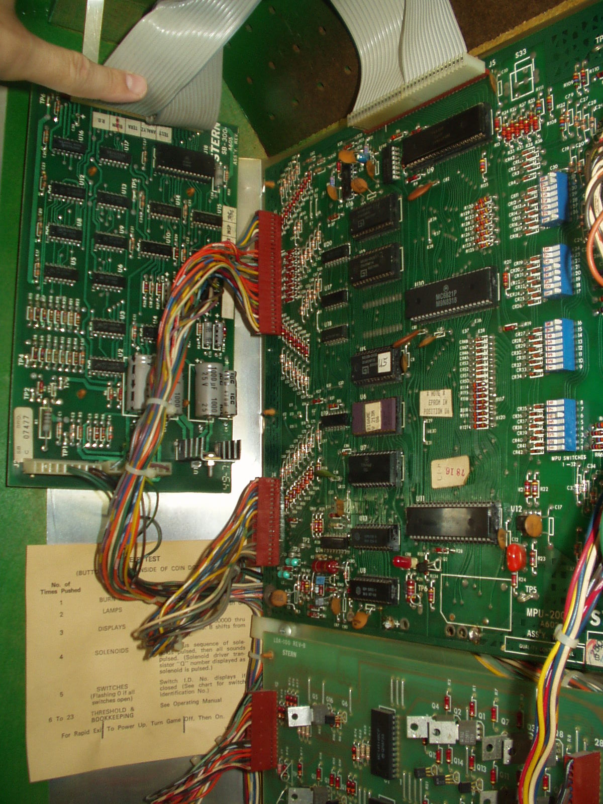
Picture from Ed Mandys big game.
The sb-300 is connected with a flat gray cable to the upper connector from the mpu-200
Then there are two additional connectors (J2), one is for the logic power (+12 V), which is used for driving the amplifier (3340 and tda2002). The other cable (J3) connects to the loudspeaker and the external volume pot.
If a vsu-100 (speech board) is also used in a game, the speech is feed through pin 5 connector j3 too the amplifier .
Theory of operation
The main circuit of the sb-300 is a progamable timer (6840). This is an obsolete motorola device. Jameco still sells them. The 6840 generates three different squarewaves in different frequencies out of the three timers. (marked q1,q2 and q3 in the schema). Two of these squarewaves (q1 and q2) are generating sounds. The third squarewave (q3) is used for the volume stepper. The 6840 is addressed direct from the mpu-200 (same way as a 6821 pia). The mpu-200 could write and read data to the 6840.
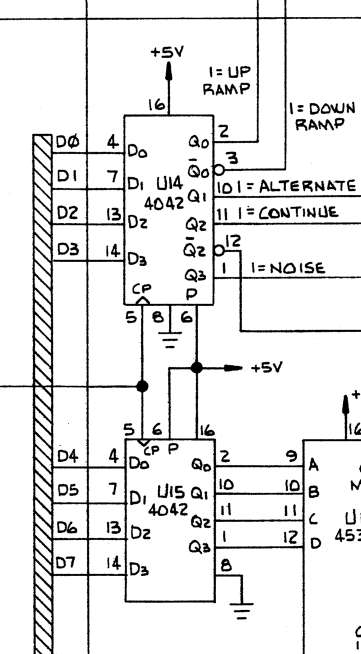
The mpu-200 can send also a soundcommand which is stored in two 4042 (u14, u15). On the board you find a noise generator (white noise with a defineable start frequency). The noise generator is located behind U15.
Then you have a volume stepper (circuit behind q3). With this circuit the mpu-200 can alter the volume of the noise generator or from a generated squarewave (q2).
Then you have an amplifier on the board with an external volume pot.
Soundgeneration:
This soundboard can produce a wide range of different sounds. During the startup of the game, the mpu-200 programs the Q3 Timer.
For producing a specific sound, the mpu-200 programs the Q2 or the Q1 timer with frequencies. Then the 6840 decreases the timer internally. The mpu-200 could read the frequencies and could changes the frequencies. With this method a smoth sound change is possible.
The 6840 uses the mpu-200 clock circuit and the sound is very sensitive to the cpu speed (this means different mpu-200 boards could generate different sounds with the same game rom...). There is an external clock circuit (see the area around tp5) who is connected to the 6840. But the mpu-200 overrides the external clock circuit with the internal clock (E).
For specific sound effects, the soundcommand is used. White noise in different frequencies could be generated and different volume effects are supported. Overall you could say the entire boards acts like a big, very improved ay-3-8910 soundchip with much more possibilities.
I think this soundboard was a great invention and better then the bally soundboards of this area.
Sometimes only a specfic circuit is defective on this soundboard. Then you have a half working soundboard. Some effects still work, others don't. Troubleshoting this board is not easy.
Testing
Check these *) points when you troubleshotin a sb-300 board.
The tests where made with a mpu-200 with meteor roms. You should be able to reproduce these tests with all other games.
You can test a sb-300 only with the gray cable on the test bench. The amplifier part will not work, (because of the missing 12 volt) but you can analyse the signal with you probe or scobe.
*) This is the first task for troubleshoting. Check this cable for continuity from the MPU-200 to the soundcard. (pin by pin)
*) Another source of problems are the 5101 chips on the mpu-200. This chips must be quick enought (suffix -1), otherwise you will have some trouble (for example spinner sound in meteor is garbled)
*) And then of course check the voltages at the different testpoints (tp4 + 5v, tp6 ground, tp2 + 12v)
*) When the mpu-200 doesn't start when the soundcard is connected then remove the 6840 chip from the soundcard. A damaged 6840 chip can hold down the databus and prevent the mpu-200 from startng.
During the power on of your pinball you should hear 7 or 8 boings. During solenoid test (20-29) you should hear specific sounds.
These solenoids test and the startup sound are in my opion all the same sounds on all sb-300 games.
Here you have the startup wave startup.wav and a part of the solenoid test sound (starting from solenoid 23 I think) solenoid test sound .
These are the main circuits from the soundcard:
Progamable timer: 6840 U18
Command memory: 4042 U14 and 15
Noise generator: 4536 U11, 4562 U6
Volume stepper: 4516 U12, 4051 U2 and U3
Amplifier: 3340 U4 and tda2002 U1
programable timer
The 6840 is nothing more than a big programable timer. Here is the datasheet.6840.pdf
This timer is able to generate three different squarewaves in different frequencies.
You can read the squarewaves at pin 6 (wave q3), pin 3 (wave q2), pin 27 (wave q1).
Wave Q3 -> This wave is used for the volume stepper.
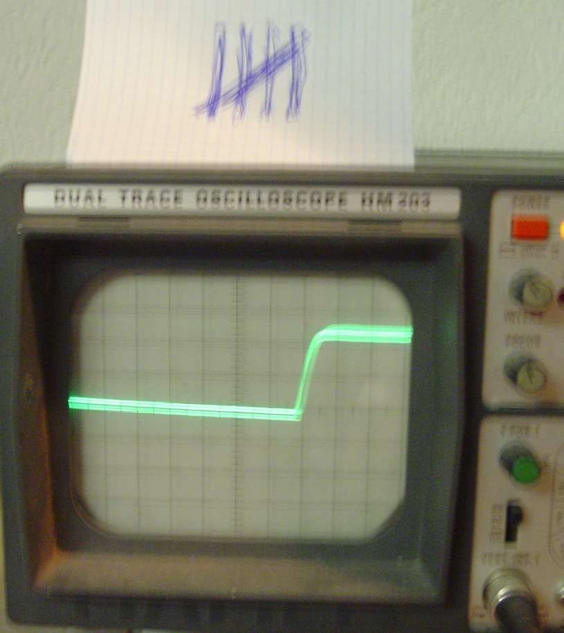
*) Direct after power on, this wave is active. You should have between 2.5 and 3.5 volt at pin 6. (or a nice squarewave if you have a scope)
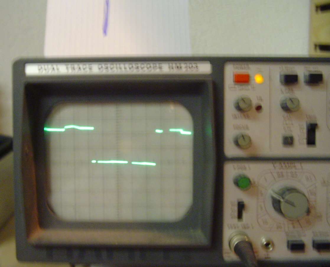
Picture 1, pin 6 direct after power on
Otherwise the 6840 is not working properly. This could have the following reasons:
- gray cable (check for continuity)
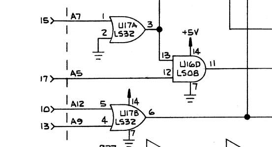
- adress decoding. These circuit decodes the adress from the mpu-200:
- the 6840 could be bad.
Wave Q2 -> This wave is used for the sounds during gameplay, the volume control is done with the volume stepper.
Wave Q1 -> This wave is used for the sounds during gameplay, the volume is always 100 % (and not controlled by the volume stepper)
You can check this wave in the following way:
*) Put the pinball into solenoid test.
During the solenoid number 20 you should here a sound. You may check cap c28 (positive side). There you should have a reading with the scope. If you don't have a reading at the cap, the 6840 is not working properly. If you have a reading and you don't hear a sound I would check the amplifier circuit.
command memory
The mpu-200 sends soundcommands to the sb-300. The actual soundcommand is stored in the U14 and U15 (both 4042).
The U14 controls the volume stepper circuit and enables the noise generator (pin 1 = 5 Volt noise generator enable)
The U15 holds the starting value for the noise circuit.
*) You can check the command memory in the following way:
Put the pinball into solenoid test. Check the voltage at U14 pin 1. During the solenoid numbers 22 - 29 the Voltage should be 5 V. During the solenoid numbers 1 - 21 you should have 0 Volt.
Put the pinball into solenoid test. Check the voltage at U15 pin 11. During the solenoid numbers 26 - 29 the Voltage should be 5 V. During the solenoid numbers 1 - 25 you should have 0 Volt.
Otherwise the command memory is not working. This could have the following reasons:
- adress decoding. These circuit decodes the adress from the mpu-200:
- one of the 4042 could be bad.
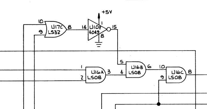
Noise generator
The noise generator uses an external clock circuit.
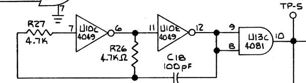
This circuit is permantly running.
*) At tp5 you should have a reading between 2 - 3 Volt.
Picture 3, TP5 after power on
Otherwise replace U10 or U13.
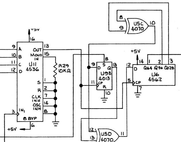
The external clock circuit feeds a 4536, this is also a timer.
The start value of this time is a part of the command memory.
The output of the timer is connected to a large 128-bit shift register (4562).
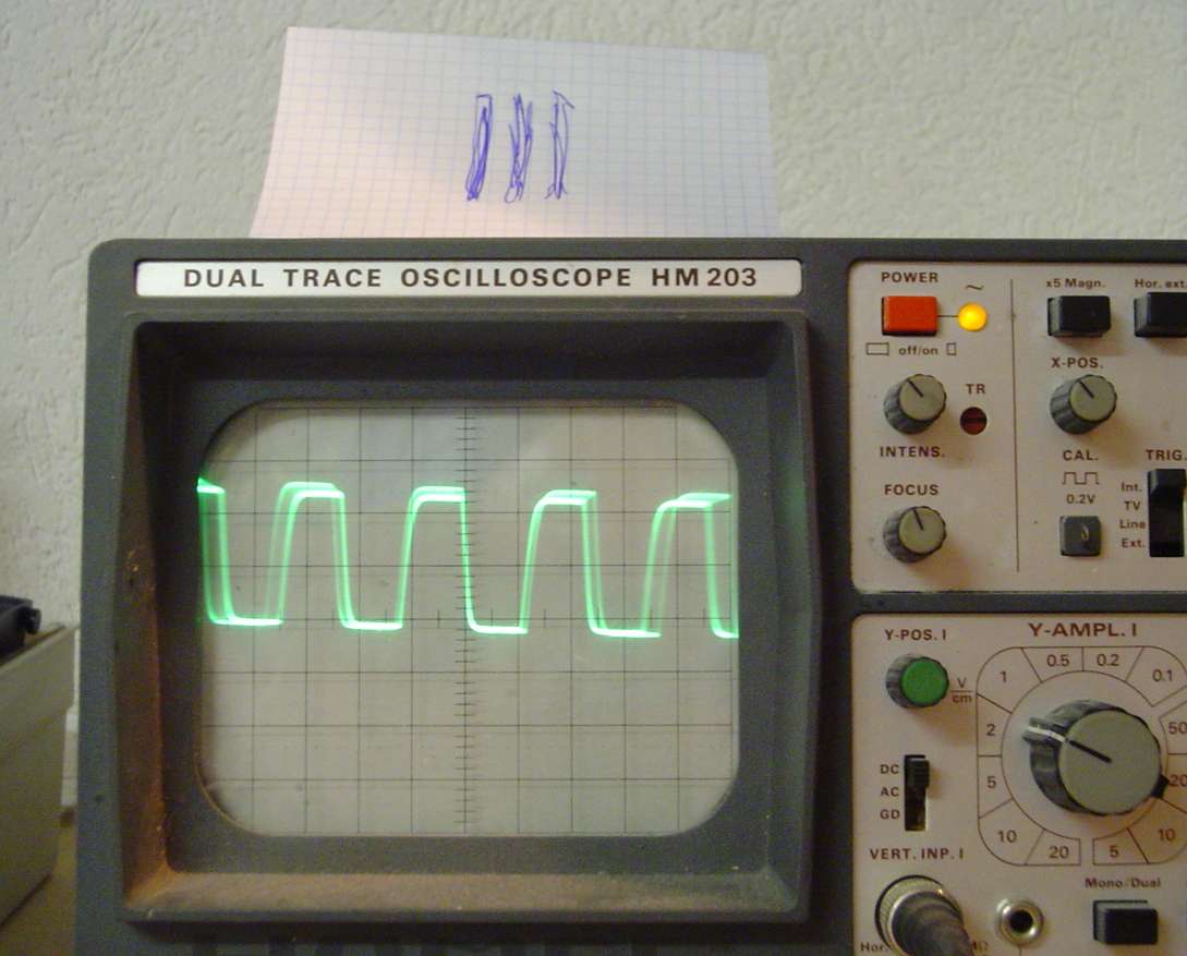
*) You can check the noise generator in the following way:
Put the pinball into solenoid test. Check the voltage at U6 pin 5. For this you need a scope.
During the solenoid numbers 1 - 21 you should see a squarewave.
Picture 4, 1 - 21 solenoid squarewave at U6 pin 5
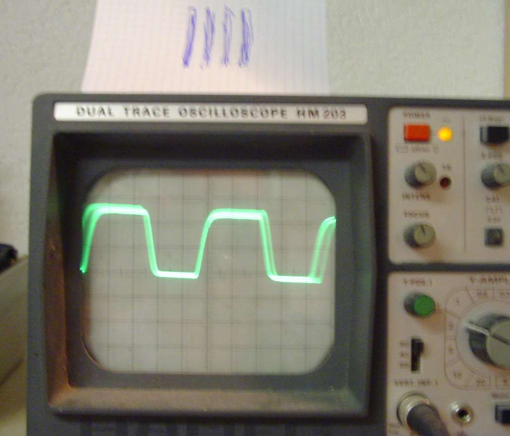
During the solenoid numbers 22 - 29 the frequencies of the squarewave changes.
Picture 5, 22 - 29 solenoid squarewave at U6 pin 5
Volume stepper
The volume stepper is controlled by the u14. The MPU-200 can specfic volume control from silent to loud. (U14 pin 1 = 5 Volt).
The MPU-200 can define alternating volume control (silent -> loud or loud -> silent).
The MPU-200 can define continue volume alternating (silent -> loud -> silent -> loud...)
First you have a 4027 (U8a a J-K Flip Flop). This flip flop is responsibile for the direction of the volume (silent -> loud or loud -> silent). The volume stepper itself is a 4516 (u12). This is a binary up / down counter. This counter is clocked by the 6840 wave q3.
The output from the counter is feed into two analog multiplexer (4051 u2 and u3). Behind these two multiplexers you find a series of resistors (r14 until r22).
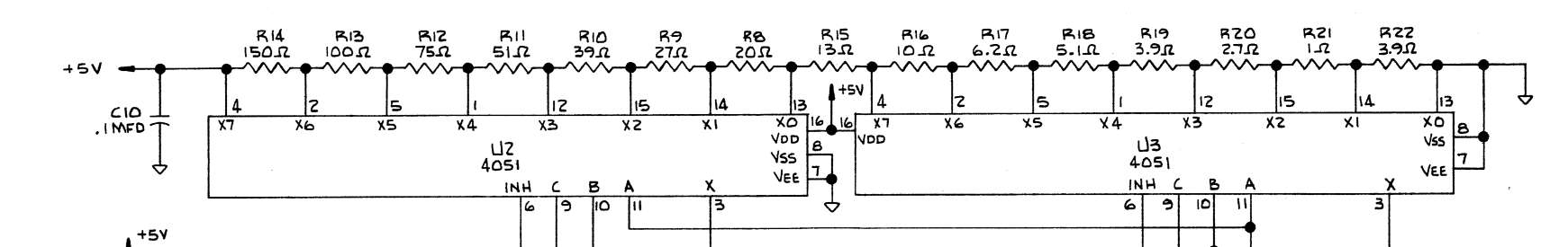
*)You can check the voltages at the resistors after power on.
From the left side (r14) to the right side (r22) you should get a descending voltage starting from 5 V to 0 V at the different resistors.
*) Put the pinball into solenoid test. Check the voltage at U12 pin 2
During the solenoid numbers 23 - 28 you see the following
sb300_DivX.avi
The "output" (a varying voltage from 0 to 5 v) of the two multiplexers (4051) is connected to the next multiplexers (4053 u7a and u7c).
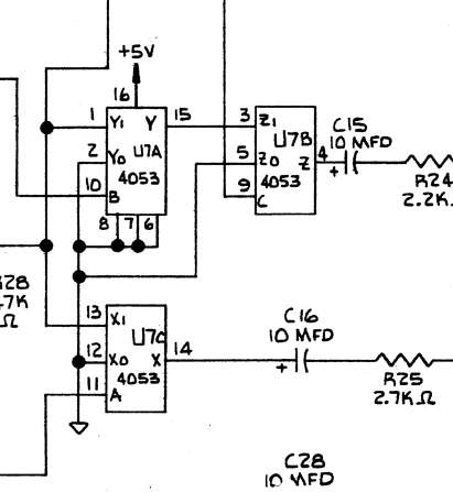
These multiplexer are digit controlled. U7a mixes the output from the volume stepper with the digital output from the the noise generator (u6). After U7a there is an additonal multiplexer. This multiplexer is controlled by the controller memory. (4042 U14)
U7c mixes the output from the volume stepper with the wave Q2 from the 6840.
So the mpu-200 can controll the volume from the noise generator and from the generated sound.
Amplifier:
*) If you don't hear any sound, replace all caps on the board.
Mail me