Hardware:
The digits of the displays are adressed by the connector J1 / Pin one (rightmost) to six (leftmost)

In 1981 bally started to use the seventh pin for adressing the seventh digit.
Unfortenally for earlier bally pinballs, the seventh pin is used for adressing the sound card (as-2518-32)
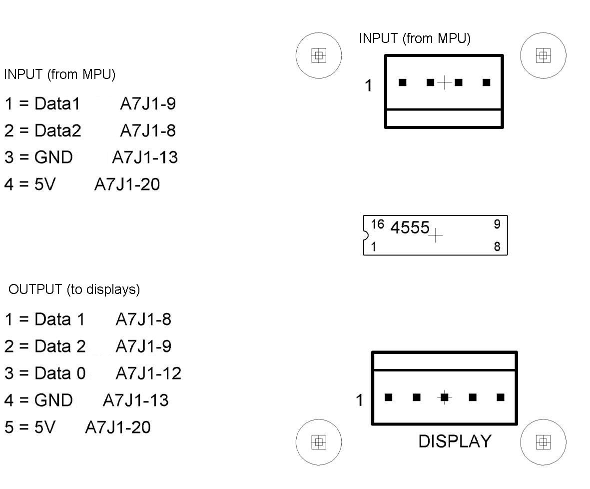
So I built a little pcb, which uses the J1 Pin 5 and pin 6 to address the 5 , the 6 and the 7 digit with the help of the 4555 chip. (You find this chip for example on early aux lamp boards like centaur).
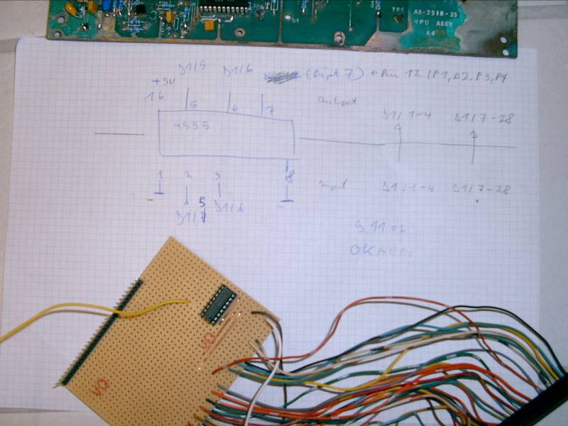
Wiring is quite simple:
Connect: Pin 16 (4555) to + 5 (Mpu)
Pin 1 (4555) to Pin 8 (4555) to ground (Mpu)
Pin 2 (4555) to J1 Pin 5 (Mpu)
Pin 3 (4555) to J1 Pin 6 (Mpu)
Pin 5 (4555) to J1 Pin 5 (Displays)
Pin 6 (4555) to J1 Pin 6 (Displays)
Pin 7 (4555) to every 7-Digit Player Displays Pin 12
J1 Pin 1-4 (Mpu) to J1 Pin 1-4 (Displays)
J1 Pin 7-28 (Mpu) to J1 Pin 7-28 (Displays)
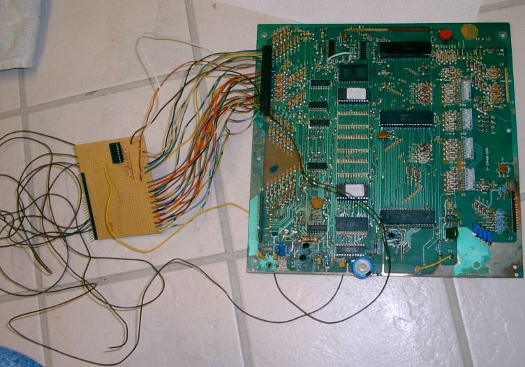
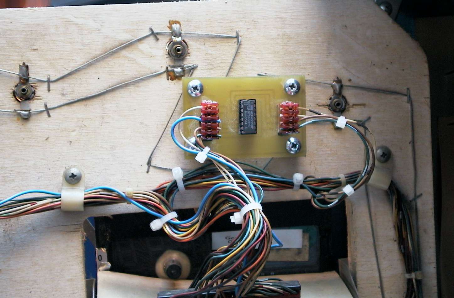
Here is the result:
Software:
In the displays update routine every digit is adressed with one bit through the Pia U11 (Pin 1 to 6).
The seventh digit is adressed with two bits (Pin 5 and Pin 6). The Ic 4555 (which is a 1 to 4 decoder) is used to make out of two input lines (Pin 5 and 6) three output lines (Pin 5, 6, and 7).
So I could now adress 7 Digit Displays.
Internally in this U6 Rom every variable is 6 digit wide. So I took an idea from Piero Cavina , and dived internally every score by 10. In the display update routine I added a fake 0 at the rightmost position. During the selftest (selftestnumber > 4) I supress this fake 0.
And here is the result:

A fellow pinball collector (volley02) in germany built a little pcb and mounted it on the backside of the displays.
Downside:
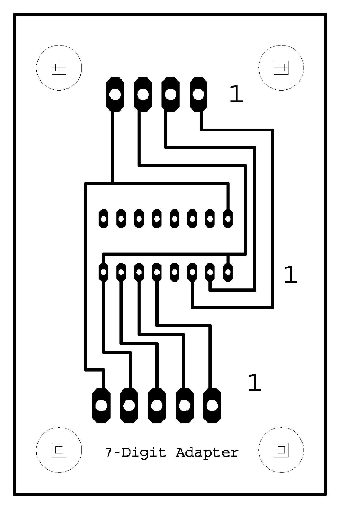
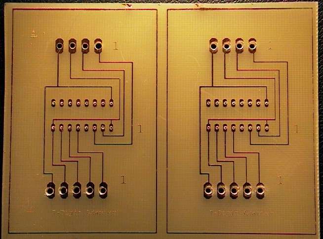
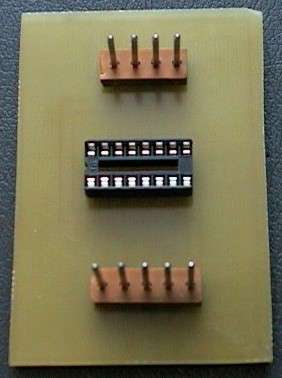
Upper side
Make sure that the PCB do not touch the lamp wires and use plastic spacers.
Mail me